Modbus Exception 05 (Acknowledge): Causes, Protocol Handling & PLC Fixes (2026)
In industrial automation, encountering an exception response from a Modbus slave is a routine diagnostic task. Most automation engineers are intimately familiar with common exceptions such as 01 Illegal Function, 02 Illegal Data Address, or 03 Illegal Data Value. However, when a supervisory SCADA system, DCS controller, or testing utility like Modbus Poll suddenly displays Modbus Exception Code 05 (Acknowledge / 0x05), confusion often arises.
Unlike errors that signify an invalid register or malformed packet, Modbus Exception 05 is a specialized handshake signal: "I have received your command and it is valid; I am working on it right now, but it will take substantial time to complete." If your PLC or master software is not programmed to expect this asynchronous behavioral pattern, it will interpret the acknowledgment as a communication failure, aborting process sequences prematurely.
This technical guide dissects the exact protocol specification of Modbus Exception 05, examines the industrial root causes that trigger it, demonstrates hex-level wire frame captures, and provides concrete PLC ladder logic, structured text, and Python handling patterns to eliminate spurious faults.
Need to Test Modbus Exception Handling Safely?
Do not test timeout logic on live multi-million dollar chemical reactors or high-power motor skids. Download ModbusSimulator to emulate slave devices that generate Exception 05 on demand, verifying your master retry state machines safely on your PC.
1. The Formal Protocol Specification of Exception Code 05
According to the official Modbus Application Protocol Specification V1.1b3 (Section 7: Modbus Exception Responses), Exception 05 is formally defined as:
| Exception Code | Name | Official Definition |
|---|---|---|
| 05 (0x05) | Acknowledge | "Specialized use in conjunction with programming commands. The server (or slave) has accepted the request and is processing it, but a long duration of time is required to do so. This response is returned to prevent a timeout error from occurring in the client (or master). The client (or master) can subsequently issue a Poll Program Complete query to determine if processing is completed." |
In standard Modbus operation, the master sends a request and waits synchronously for either normal data or an immediate error. If the slave device took several seconds to perform an internal physical operation (such as writing to slow EEPROM or recalibrating a strain gauge), the master's response timeout (typically 500 ms to 2000 ms) would expire, registering a fatal Timeout Error.
To prevent this, the Modbus standard specifies Exception 05: the slave replies immediately with code 0x05, letting the master know the connection is healthy, the packet was parsed successfully, and the device is now engaged in completing the command.
2. Exception 05 vs. Exception 06: Understanding the Critical Difference
Engineers often confuse Exception 05 (Acknowledge) with Exception 06 (Slave Device Busy). The operational distinction is fundamental:
| Feature | Exception 05: Acknowledge | Exception 06: Slave Device Busy |
|---|---|---|
| Meaning | Command accepted and currently executing in background. | Command rejected because device is busy with another task. |
| Master Action | DO NOT resend command. Wait and poll status flag. | Resend entire command after a delay. |
| Risk of Resending | Duplicate execution, buffer overflow, or state corruption. | None; device simply re-evaluates availability. |
| Typical Use Case | EEPROM flashing, recipe transfers, batch cycle start. | Local HMI operator override, background diagnostic sweep. |
3. Anatomy of a Modbus Exception 05 Packet on the Wire
When a Modbus slave returns an exception, it modifies the original Function Code by setting the high bit (OR-ing with 0x80) and appends the single-byte Exception Code.
Example Scenario: Master Writes Multiple Registers (FC 0x10)
Suppose a master sends a Write Multiple Registers command (Function Code 16 / 0x10) to initiate an offline zero-calibration on a smart Coriolis mass flow meter at Slave ID 0x01:
01 10 03 E8 00 02 04 00 01 00 00 [CRC_LO] [CRC_HI]
│  │  └───┬───┘ └───┬───┘ │  └────┬────┘
│  │      │         │     │       └─ Data values: 0x0001, 0x0000
│  │      │         │     └─ Byte count: 4 bytes
│  │      │         └─ Register count: 2 registers
│  │      └─ Starting register: 1000 (0x03E8)
│  └─ Function Code: 16 (0x10)
└─ Slave ID: 1
Because the flow meter's zero-calibration routine takes 15 seconds of fluid stabilization, the slave cannot reply with the standard FC 0x10 confirmation immediately. Within 20 ms, it responds with Exception 05:
01 90 05 [CRC_LO] [CRC_HI]
│  │  │
│  │  └─ Exception Code: 0x05 (Acknowledge)
│  └─ Exception Function Code: 0x90 (0x10 | 0x80)
└─ Slave ID: 1
In a Modbus TCP environment, the MBAP Header wraps this 2-byte PDU:
[Transaction ID: 0x0001] [Protocol ID: 0x0000] [Length: 0x0003] [Unit ID: 0x01] [FC: 0x90] [Exception: 0x05]4. Primary Industrial Causes of Exception 05
When you see Exception 05 in your telemetry or SCADA logs, it typically stems from one of four scenarios:
1. Non-Volatile Flash / EEPROM Write Cycles
Industrial instruments such as PID temperature controllers, variable frequency drives (VFDs), and power meters store critical parameters in non-volatile EEPROM. Writing a new set of 20 parameters requires page erase cycles that take 100 ms to 500 ms. If the device firmware runs single-threaded, it emits Exception 05 while the EEPROM controller writes the memory blocks.
2. Internal Calibration and Self-Test Routines
Triggering an automated zero-point calibration, span adjustment, or diagnostic sensor self-test via a register write prompts the slave microprocessor to execute analog measurements over multiple power line cycles. The instrument acknowledges acceptance immediately via Exception 05 to retain the master connection.
3. Physical Actuator or Relay Interlock Timing
Certain motor-operated valves (MOVs) and high-voltage circuit breakers map position commands to Modbus coils. When commanded to stroke from closed to open, the internal slave controller returns Exception 05 to indicate the motor contactor has energized and the physical transit is underway.
4. Firmware Updates and Recipe Uploads
In modular batch processing, sending a complete production recipe (comprising hundreds of holding registers) triggers cyclic redundancy validation and internal memory reorganization. The slave issues Exception 05 until the data block is validated.
5. How to Handle Exception 05 in PLC & Master Software
A naive master implementation treats any byte with the high bit set as a communication error, raising an alarm or immediately retrying the transmission. Retrying a command that is already executing in the slave is hazardous. Here is the correct state machine architecture:
  [SEND COMMAND] ──► (Transmitted to Slave)
         │
         ▼
  [WAIT RESPONSE]
         │
         ├── Normal ACK ──────────► [COMMAND SUCCESS]
         │
         ├── Exception 05 ────────► [SET STATUS = PROCESSING]
         │                                 │
         │                                 ▼
         │                          [START POLLING TIMER]
         │                                 │
         │                                 ▼
         │                          [READ STATUS REGISTER (FC 03)]
         │                                 │
         │                                 ├── Busy (Bit = 1) ──► [DELAY & LOOP]
         │                                 │
         │                                 ├── Ready (Bit = 0) ─► [COMMAND COMPLETED]
         │                                 │
         │                                 └── Timeout Expired ──► [ALARM: OPERATION TIMEOUT]
         │
         └── Other Exception ─────► [HANDLE SPECIFIC ERROR (01, 02, etc.)]
Structured Text (IEC 61131-3) Implementation Example
The following Structured Text pattern illustrates how to handle an Exception 05 in a Siemens TIA Portal, Rockwell Studio 5000, or CODESYS controller:
CASE nStep OF
    0: (* Idle State - Ready for trigger *)
        IF bTriggerCommand THEN
            bBusy := TRUE;
            bDone := FALSE;
            bError := FALSE;
            tTimeoutTimer(IN := FALSE);
            nStep := 10;
        END_IF;

    10: (* Send Write Command to Slave *)
        ModbusMasterWrite(
            Execute := TRUE,
            SlaveAddress := 1,
            Function := 16,
            StartAddress := 1000,
            Quantity := 2,
            DataBuffer := aWriteData
        );
        nStep := 20;

    20: (* Evaluate Master Block Response *)
        IF ModbusMasterWrite.Done THEN
            (* Direct success without delay *)
            bDone := TRUE;
            bBusy := FALSE;
            nStep := 0;
        ELSIF ModbusMasterWrite.Error THEN
            (* Check if error code corresponds to Exception 05 (0x05) *)
            IF ModbusMasterWrite.ExceptionCode = 5 THEN
                (* Slave acknowledged - operation underway *)
                tPollDelay(IN := FALSE);
                tTimeoutTimer(IN := TRUE, PT := T#30S);
                nStep := 30;
            ELSE
                (* Real fault: 01, 02, 03, 04, 06, etc. *)
                bError := TRUE;
                nErrorId := ModbusMasterWrite.ExceptionCode;
                bBusy := FALSE;
                nStep := 0;
            END_IF;
        END_IF;

    30: (* Polling Loop: Wait for device to finish *)
        tTimeoutTimer();
        IF tTimeoutTimer.Q THEN
            bError := TRUE;
            nErrorId := 16#E005; (* Operation timed out *)
            bBusy := FALSE;
            nStep := 0;
        ELSE
            tPollDelay(IN := TRUE, PT := T#500MS);
            IF tPollDelay.Q THEN
                tPollDelay(IN := FALSE);
                nStep := 40;
            END_IF;
        END_IF;

    40: (* Poll Device Status Register *)
        ModbusMasterRead(
            Execute := TRUE,
            SlaveAddress := 1,
            Function := 3,
            StartAddress := 1002, (* Status Register *)
            Quantity := 1,
            DataBuffer := aStatusBuffer
        );
        nStep := 50;

    50: (* Check Status Register *)
        IF ModbusMasterRead.Done THEN
            (* Check if device reported completion (e.g. Bit 0 == 0) *)
            IF (aStatusBuffer[0] AND 16#0001) = 0 THEN
                bDone := TRUE;
                bBusy := FALSE;
                nStep := 0;
            ELSE
                (* Still processing - return to wait timer *)
                nStep := 30;
            END_IF;
        ELSIF ModbusMasterRead.Error THEN
            bError := TRUE;
            nErrorId := ModbusMasterRead.ExceptionCode;
            bBusy := FALSE;
            nStep := 0;
        END_IF;
END_CASE;
Python (pymodbus) Handling Example
If you are developing automated testing scripts or IIoT gateways using Python, handle Exception 05 using explicit exception catching:
import time
from pymodbus.client import ModbusTcpClient
from pymodbus.pdu import ExceptionResponse

def execute_extended_operation(client, slave_id, target_reg, values):
    print(f"[*] Sending write command to Slave {slave_id}...")
    response = client.write_registers(target_reg, values, unit=slave_id)

    # Check if slave returned an exception
    if isinstance(response, ExceptionResponse):
        if response.exception_code == 5:
            print("[+] Received Exception 05 (Acknowledge): Operation accepted by slave.")
            print("[*] Entering status polling loop...")

            # Poll status register 1002 every 500ms (max 30s timeout)
            start_time = time.time()
            while time.time() - start_time < 30:
                time.sleep(0.5)
                status_resp = client.read_holding_registers(1002, 1, unit=slave_id)
                if not isinstance(status_resp, ExceptionResponse):
                    status_flag = status_resp.registers[0]
                    if status_flag == 0:  # 0 indicates completion
                        print("[✓] Operation completed successfully by slave!")
                        return True
                    else:
                        print(f"[-] Still processing (Status: 0x{status_flag:04X})...")

            raise TimeoutError("Slave failed to complete operation within 30 seconds.")
        else:
            raise RuntimeError(f"Modbus Exception {response.exception_code} occurred.")

    print("[✓] Operation completed immediately.")
    return True

# Example Usage
if __name__ == "__main__":
    client = ModbusTcpClient("192.168.1.100", port=502)
    client.connect()
    try:
        execute_extended_operation(client, slave_id=1, target_reg=1000, values=[1, 0])
    finally:
        client.close()
6. How to Simulate and Verify Exception 05 with ModbusSimulator
Testing edge-case communication exceptions on real industrial hardware is fraught with operational risk. Simulating these conditions allows you to harden your PLC and SCADA code ahead of commissioning.
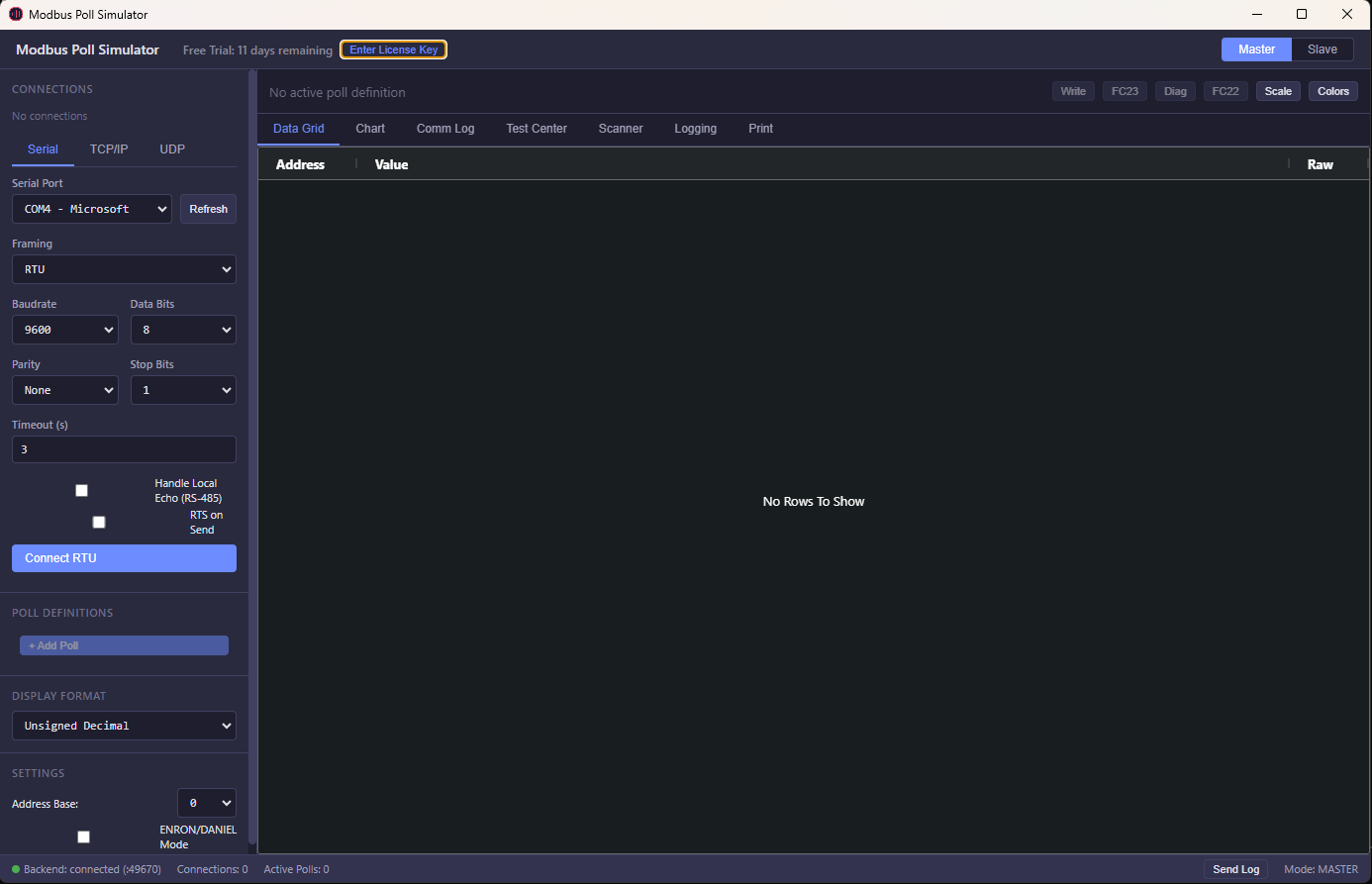
Figure 1: Configuring deterministic Modbus Exception 05 responses in ModbusSimulator.
With ModbusSimulator, you can configure your virtual slave device to:
- Respond with
Exception 05 (Acknowledge)whenever Function Code 16 (Write Multiple Registers) is called on specific address ranges. - Simulate an asynchronous background task by toggling a designated status register from
1(Busy) to0(Ready) after a configurable delay (e.g. 5,000 ms). - Inspect your master controller's serial and TCP Wireshark logs to guarantee your polling logic handles the response without triggering false-positive plant alarms.
7. Summary Diagnostic Checklist
| Check | Investigation Step | Corrective Action |
|---|---|---|
| 1. Slave Capability | Review the vendor's Modbus register map manual. | Confirm whether the command is an asynchronous background action intended to return Exception 05. |
| 2. Master Retry Logic | Check if the master is re-transmitting write commands. | Disable rapid retries on write commands; switch master state to poll status registers instead. |
| 3. Timeout Configuration | Inspect overall process step timeout timers. | Increase the upper ceiling of the operation timeout (e.g., 30s) while keeping Modbus packet timeout at standard 1000ms. |
| 4. Software Verification | Emulate the slave using ModbusSimulator. | Verify your PLC ladder logic state machine transitions properly from Acknowledge to Poll to Done. |
Frequently Asked Questions (FAQs)
What is Modbus Exception Code 05 (Acknowledge)?
Modbus Exception Code 05 (Acknowledge / 0x05) is an official standard response defined in the Modbus Application Protocol Specification. It signals that the slave device received and accepted the master's request and is actively processing it, but requires a significant duration of time to complete the action. The response prevents a master timeout while background work progresses.
How does Exception 05 differ from Exception 06 (Slave Device Busy)?
Exception 06 (Slave Device Busy) means the slave is currently occupied and rejected the command entirely; the master must retry the write later. Exception 05 (Acknowledge) means the slave accepted the command and is currently executing it; the master must not resend the write, but rather poll for completion.
Which Modbus operations typically trigger Exception Code 05?
Writing batch parameters to slow EEPROM/flash, initiating self-test or zero-calibration sequences on smart sensors, and commanding physical motor actuators or high-voltage switchgear commonly trigger Exception 05.
How should a SCADA or PLC master respond when receiving Exception 05?
The master should transition to an asynchronous waiting state, periodically polling a designated status register or reading a digital completion flag until the operation finishes or a supervisory timeout expires.
Can Modbus Poll automatically handle Exception 05?
Standard Modbus Poll installations typically treat Exception 05 as an error because generic software cannot predict which status register indicates completion. Handling Exception 05 requires custom polling logic or test scripting.
How can I simulate Modbus Exception Code 05 in ModbusSimulator?
In ModbusSimulator, assign an Exception 05 rule to your target register range. The simulator will return 0x05 immediately, enabling you to test and validate your master PLC state machines without hardware.
Is Exception 05 supported over both Modbus RTU and Modbus TCP?
Yes. The exception code is part of the core Modbus PDU and is identically supported across Modbus RTU (serial RS-485), Modbus ASCII, and Modbus TCP/IP networks.
Master Modbus Simulation & Troubleshooting
Test master polling routines, simulate slave devices, and debug complex exception codes with zero hardware risk.